Laser scanning technology
Being one of the most progressive directions in the development of remote sensing, airborne laser scanning (hereinafter referred to as ALS) is increasingly used in such industries as engineering surveys, land management, cadastre, forestry and many others. In combination with digital aerial photography, ALS makes it possible to obtain a three-dimensional array of laser reflection points (hereinafter referred to as Point Clouds), with a density of up to several hundred points per 1 m2 and an accuracy of determining their coordinates of 3-5 cm in plan and in height. In fact, this is a digital model of the true surface, the basis for orthophotomaps, digital topographic plans at a scale of 1:500 and smaller, three-dimensional relief models, buildings and structures.
The essence of the ALS technology lies in the spatial reference of the Point Clouds, which is carried out on the basis of the data of the main components of the scanning system: a sensor (LiDAR) with the function of measuring distances, a GNSS receiver with the function of recording satellite observation data to calculate the spatial position and an inertial unit with the function records of angular speeds and linear accelerations for measuring spatial orientation. Such a set of initial data makes it possible to uniquely determine the coordinates of each laser point by solving a direct geodetic problem.
The first stage of the ALS is the collection of Earth remote sensing data - shooting from a drone or a manned aircraft. When making flight plan, it is necessary to take into account the desired overlap between the "routes" – Point Clouds corridors obtained when moving along the working route (section of the trajectory between turns), the importance of minimizing the deviation from the specified flight altitude and the difference between the maximum range and the working scanning height. Let's imagine an aircraft performing a flight for the purpose of conducting ALS along the Y-axis (Fig. 1).
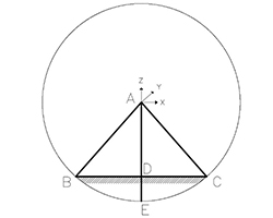
Fig. 1. Scheme for calculating the overlap with a known maximum range and a given scanning height
The UAV is equipped with a scanning system of the AGM-MS series. Let us draw a circle near the flight axis with a radius equal to the maximum scanning range. The width of the Point Clouds corridor obtained when moving along the trajectory at the working height "AD" is equal to the segment "BC". As the flight altitude increases to the maximum scanning range ("AE", as well as "AB" and "AC"), the width of the corridor tends to zero (point E). To obtain a 50% overlap between "routes", we should set the distance between adjacent lines equal to the segment "BD" ("DC"). The overlap is established in order to ensure the uniformity of the distribution of the point density value, to exclude optical shadows from high-altitude objects, and to control the quality of ALS data by assessing the convergence of adjacent corridors.
The GNSS receiver and inertial navigation system installed in the scanning system, together with the data of the ground-based GNSS receiver (base station), serve to implement the next stage of the technology - to obtain a combined trajectory solution. The solution is a sequence of points with exact coordinates and orientation angles calculated by the differential method, obtained after integrating the data of the inertial block. The discreteness of the trajectory is determined by the recording frequency of the inertial navigation system (for AGM-PS is 500 Hz). In other words, the movement of the scanning system in space for 1 s is recorded by 500 points with attributes of coordinates and orientation angles (Fig. 2).
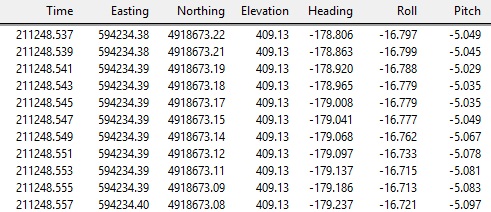
Fig. 2. Trajectory
The quality of the calculated trajectory is usually assessed by two main indicators, namely, the difference in determining the calculated values of coordinates and orientation angles between the direct and reverse solutions of the trajectory. AGM Systems offers users two software products with trajectory solution functionality: AGM PosWorks Web and AGM ScanWorks Pro. Figures 3, 4 show graphs of the change in the ambiguity of the combined trajectory solution in determining the calculated coordinates and orientation angles using the AGM ScanWorks Pro software as an example.
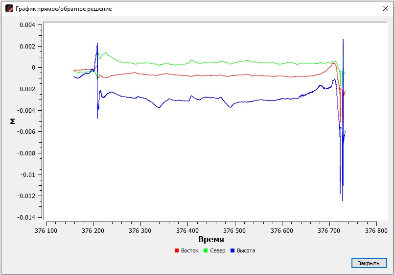
Fig. 3. Change in the ambiguity of the calculated coordinates

Fig. 4. Change in the ambiguity of the calculated orientation angles
The presence of a ready-made trajectory solution leaves the user before the final stage of ALS data output - obtaining a coordinated Point Cloud and exterior orientations for photos. In the delivery set of the hardware and software system of the AGM-MS series, this task is performed by the AGM ScanWorks software. On Figures 5 and 6 show examples of a Point clouD colored by the absolute height attribute and a file of external orientations for photos for subsequent orthomosaic compilation.
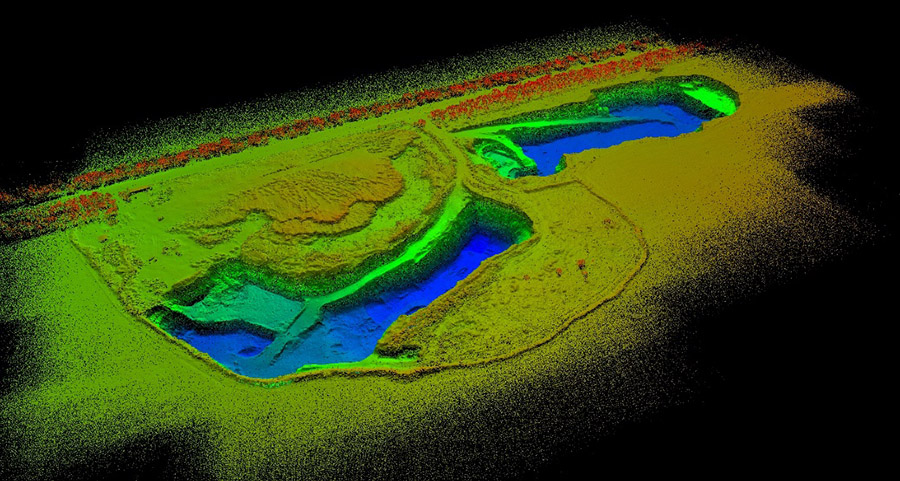
Fig. 5. An example of Point Cloud obtained by the ALS method
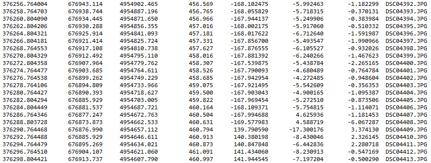
Fig. 6. External orientations for photos
The content of further post-processing of the Point Clouds depends on the final task of the work. Let us briefly consider the use of laser scanning data in the creation of digital topographic plans (hereinafter referred to as DTP). Here, one of the most important stages in the processing of a raw Point Cloud is the classification of the initial array for the generating of digital elevation model (DEM) - the future basis for isolinear elevation modeling in DTPs of different scales (Fig. 7).
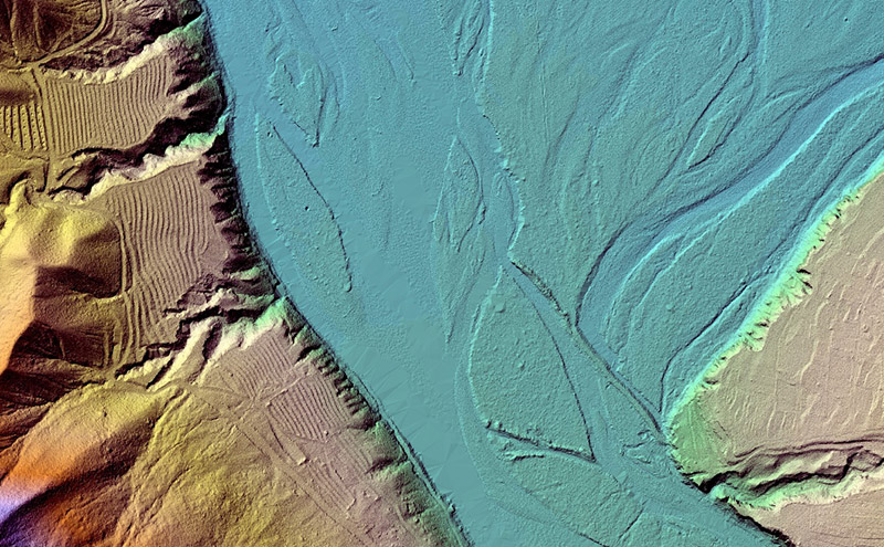
Fig. 7. An example of a high-resolution raster digital elevation model with a hillshade
An integral part of this stage is the generalization of the points of the classified class "Ground" according to the scale of the issued plans.
One of the most important products for cameral interpretation to make a topographic map is a digital orthomosaic. Creation of an orthomosaic is possible using two main methods: phototriangulation by overlapping stereopairs of photos and direct positioning by ready-made calculated exterior orientations. In both cases, a digital elevation or surface model is also required for projecting photos. At the same time, with the using of ready-made Point Clouds of the "Ground" class, obtained by the ALS method, the producing of orthomosaic is significantly accelerated. Fig. 8 shows a digital elevation model, a digital orthomosaic and a topographic plan as a result of the proccess.
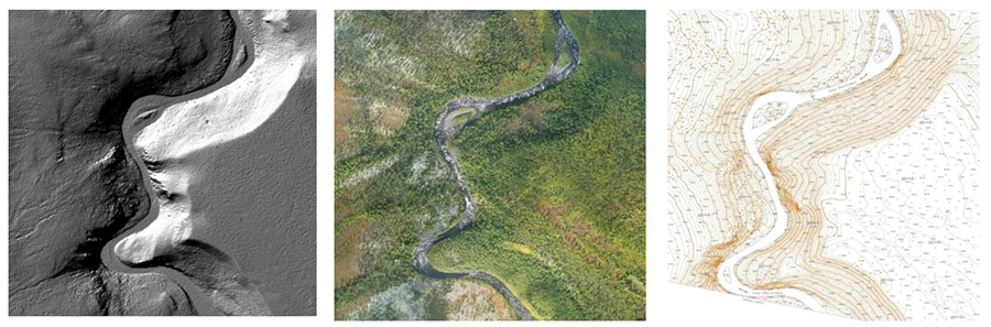
Fig. 8. DEM (in the form of hillshading), ortophotomap and topographic plan
In general, the high speed of survey, its detail, accuracy and efficiency of obtaining results due to the increasing degree of automation and simplification of remote sensing data processing make engineering surveys (especially large-scale projects) more and more unthinkable without ALS.